Descrição
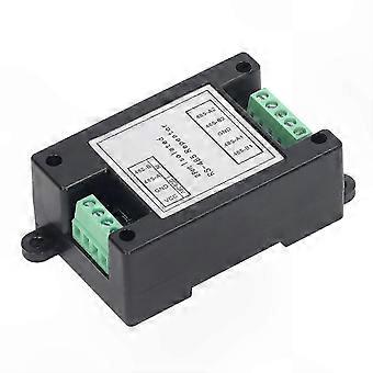
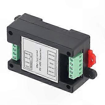
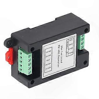
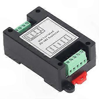
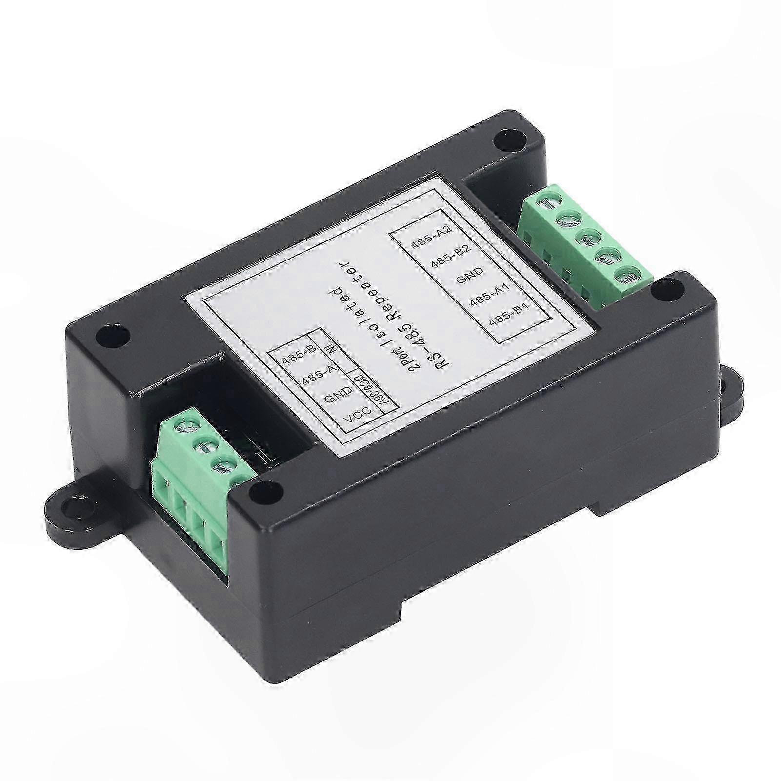
Feature: 1. Complete Isolation of Communication: The repeater module adopts an industrial-grade design, providing complete communication isolation, stable and reliable performance, with a transmission rate up to 300Kbps. 2. Isolated Power Module: The repeater module includes a built-in high-performance DC-DC isolated power module to achieve electrical isolation between ports. 3. 2-Channel Output: The repeater module supports 2-channel output for multi-device communication, allowing up to 256 nodes per channel with extended transmission distance. 4. Automatic Control Technology: The 2-channel repeater features automatic data flow control technology that automatically detects and manages data transmission direction. 5. Multiple Protection Measures: The 2-channel repeater provides ±15kV ESD protection, 600W dual TVS surge protection, and 2.5kV communication isolation. 6. Wide Power Supply Range: The 2-channel repeater supports a wide input voltage range of 9–36VDC with reverse connection protection and is compatible with standard DIN rail mounting. Specification: Item Type: Repeater Module Material: PP Operating Voltage: - Typical Value: DC 9–36V - Limit Value: DC 40V Power Rating: - Typical: 0.36W (9V/35mA; 12V/27mA; 24V/15mA) - Limit Value: 0.5W Operating Environment: - Typical: Temperature: -30°C to 80°C, Humidity: >95% RH - Limit Value: -40°C to 85°C Isolation Voltage: - Typical: 2000V - Limit Value: 2500V Interface Protection: - Typical: 600W Thunder Surge - Limit: 600W Load Capacity: - Typical: 1–128 Nodes - Limit: 256 Nodes Communication Distance: - Typical: 0–1500m - Limit: 2000m Communication Speed: - Typical: 300bps–115.2Kbps - Limit Value: 300Kbps Dimensions: Approx. 100 x 54 x 32mm / 3.9 x 2.1 x 1.3in Status Indicators: - Power Indicator: Red LED, stays on when powered - Data Indicator: Green LED, blinks when data is transmitted on the bus Terminal Interface Definition: - VCC: Power supply interface (DC 9–36V) - GND: Negative power supply terminal - 485 A: RS485 signal input/output positive terminal - 485 B: RS485 signal input/output negative terminal - 485 A2: Second RS485 signal input/output positive terminal - 485 B2: Second RS485 signal input/output negative terminal - GND: Isolated RS485 terminal ground, can be connected to earth or shield wire - 485 A1: First RS485 signal input/output positive terminal - 485 B1: First RS485 signal input/output negative terminal Usage Instructions: A. RS485 Wiring
Notes:
- : 1
- Use shielded twisted pair cable for RS485 communication lines, preferably with spare strands; total length should not exceed 1500 meters
- 2
- Keep wiring away from high-voltage power lines; avoid parallel routing or bundling with power cables
- 3
- RS485 bus must use a daisy-chain (hand-in-hand) topology; star or branched connections are not recommended
- 4
- Use an RS485 repeater when connecting more than 30 controllers or when cable length exceeds 500 meters
- 5
- Equipment with AC power supply and chassis must be properly grounded
- 6
- Connect the GND terminal of all RS485 devices using a shielded wire
- B
- RS485 Cable Selection Requirements: - Use 2-core shielded twisted pair cable - Copper conductor, wire diameter 0
- 5–0
- 75 mm² - Impedance: 38–88 ohms/km - Capacitance: 30–50 nF/km - Twist pitch: 20 mm (for runs under 500 meters, standards may be relaxed but must remain twisted pair) C
- Bus Configuration Limits: - The bus can connect two or more devices, with a maximum of 256 devices without repeaters
- - Maximum bus length without repeaters: 1500 meters
- - Avoid bus branches; if unavoidable: 1
- Branch length ≤ 10 meters, total bus length ≤ 800 meters, maximum 50 devices on branch lines
- 2
- Keep signal lines away from interference sources; route through low-voltage conduits
- Avoid running parallel to high-power (e
- g
- , 220V) or RF signal lines
- If parallel routing is necessary, maintain a distance of at least 0
- 5 meters
- 3
- All wire joints must be soldered or tightly crimped and sealed against moisture using waterproof tape or epoxy resin
- D
- Signal Common Ground: 1
- All devices on the same network segment must share a common signal ground to prevent common-mode interference
- 2
- For centralized power supply systems, connect the negative DC terminals of all power supplies (including devices with independent power) to form a unified signal ground, which serves as the DC power ground
- 3
- For single independent power supply setups, connect the ground (black wire) pins of all bus devices to establish a common reference
-
Identificação da Fruugo:
429148970-901555980
-
EAN:
6039563718101
Informações de segurança do produto
Consulte as informações de segurança do produto específicas para este produto descritas abaixo
As informações a seguir são fornecidas pelo revendedor independente que vende este produto.
Etiquetas de segurança do produto

Avisos de segurança:
Not suitable for children under 40 months. Choking Hazard. Adult supervision recommended
Entrega e Devoluções
Enviado dentro de 24 horas
Enviamos a partir de China.
Fazemos o nosso melhor para garantir que os produtos que encomendar lhe serão entregues na totalidade e conforme as suas especificações. No entanto, se receber uma encomenda incompleta ou itens diferentes dos que encomendou, ou existir qualquer outra razão pela qual não estiver satisfeito com a sua encomenda, poderá devolver a encomenda ou quaisquer produtos incluídos na mesma, e receber um reembolso total dos itens. Ver a política de devoluções na íntegra